


The Fundamentals of Mechanical Engineering Part 1
Let the fun begin!
Greetings my fellow Mechanical Engineers! I am collecting all the interview questions for job titles such as 'Mechanical Engineer', 'Design Engineer', 'Chassis Engineer' etc. that I can find online through websites such as Glassdoor and posting them here. To anyone who is currently looking for a new opportunity, please remember that whether you are a college graduate or an experienced engineer, companies always like to focus on the fundamentals. Through my close to 8.5 years of experience working in the Automotive Industry, I can affirm that many a times interviewers like to focus on our fundamentals. If you are an experienced engineer, there will definitely be more focus on the technical challenges you have resolved in your current job or your previous job however they would also be very keen to understand how good you are at your basics. Below are a bunch of questions from my personal interview experiences as well as everything I could find through google.
Note: The answers to these questions are based on the information found online through several helpful websites and YouTube videos and from books.
Q1. Explain stress-strain curve. (VERY VERY VERY IMPORTANT TO KNOW)
Voila! This is a question that I have been asked in at least 3 different interviews with 3 different companies. This question can be asked something in the lines of "What is the relationship between stress & strain?” or “What do you know about the Young’s Modulus?
How can us engineers design any component without understanding the component’s limitations to withstand loads??!! Ok, so let’s dig into the details!
A1. Instead of directly jumping into Hooke’s law, let us first understand what exactly the meaning of stress and strain is.
Stress and strain are the fundamentals concepts used to describe how a body responds to external loads.
STRESS:
As an example, let’s look at a solid bar with a cross sectional area, A being externally loaded by a force, F along its axis (Uniaxial Loading).
Two cases are presented in the image below:
Case 1: Bar being pulled in tension
Case 2: Bar being compressed
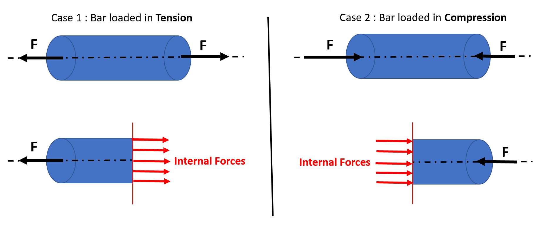
At any point on the bar, when we make an imaginary cut illustrated by a red line in the image above, there will be internal forces acting on the body along its cross-section and these internal forces are perpendicular to the imaginary cut. These internal forces are developed such that they resist the external force and are evenly distributed along the area of cross-section.
The effect of internal force will be equal to external force to maintain equilibirum.
Therefore, Stress (σ ) can be described as the internal force (F) per unit area (A) and is given by the equation:
σ = F/A
Note that the definition and equation above are only valid for Normal Stress. There is also another type of Stress called Shear Stress and this is something we will look at later.
STRAIN:
Let us look at a bar with length, L that is fixed on one end and the other end is loaded as shown in the image below. Due to the applied load and loading direction, there will be some amount of deformation in the bar that can be expressed as ΔL.

Therefore, Strain (ε) can be described as the change in length (ΔL) divided by the original length of the bar (L) and is given by the equation:
ε = ΔL/L
Strain has no units and can be expressed in percentage.
Note that the definition and equation above are only valid for Normal Strain. There are also Shear Strain and Volumetric Strain which we will review at another time.
Now let us finally look at the relation between Stress vs. Strain.
Stress-strain graph can be obtained by performing a tensile test on a component with a specific material. Tensile test is where a component is uniaxially loaded and the output would be a stress-strain curve which lets us study the amount of deformation occurred on the component for different loading conditions.
Below is a stress-strain curve for a component made of material steel. There are two regions in the curve : Elastic & Plastic
Elasticity of a material can be defined as its ability to revert back to original shape when the applied load is removed.
Plasticity of a material can be defined as the permanent deformation of the material and cannot revert back to original shape when the applied load is removed.
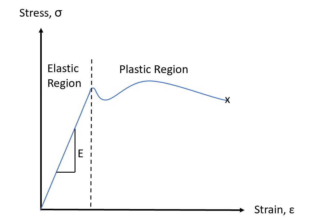
The relation between stress & strain in the elastic region as shown in the curve below is linear. This indicates that for most materials, the stress is proportional to strain in the elastic region. This is knowns as Hooke’s Law and is given by the equation:
σ = Eε ,
E in the equation is called Young’s Modulus or Modulus of Elasticity and is expressed as the same SI unit of Stress i.e. Pascal (Pa)
Q2. What is the difference between Strength vs Stiffness of a material?
This is another important question that I have been asked once in an interview and I must admit, I goofed up while answering this question and till date I feel embarrassed thinking about my answer :|
A2. Material Strength is a very important property. It can be defined as the ability of a material to withstand stress or applied loads before it yields or fractures. Strength is of two types: Yield Strength & Ultimate Tensile Strength
Stiffness, on the other hand, refers to the ability of a material to resist deformation / bending / deflection under the applied load and is measured by Young’s Modulus.
From the strain-strain curve of steel below, we can conclude the following:
Yield Strength is where the material begin to yield to the applied loading. Therefore, it can be defined as the measure of stress at which the material begins to deform plastically.
Ultimate Tensile Strength is defined as the measure of the maximum stress that the material can handle before failure.

A stronger material does not mean it is very stiff and vice versa. This can be explained by an example of a rubber band vs glass. A rubber band is not rigid. It stretches a lot for a very small amount of load applied, whereas a glass is very rigid under a small amount of load. It doesn’t flex or bend until a greater amount of load is applied at which point it breaks. Similarly, potato ships are a good example of being rigid under a very small load.
Q3. How does the strength to weight ratio of Aluminum compare to Steel?
This question could be asked by an interviewer to gauge your understanding of why Aluminum is a popular choice especially in the automotive and/or aerospace industry.
A3. Strength to weight ratio, as the terms says it all, is the strength of a material divided by its mass. Let us answer this with an example below.
Consider two bars of exactly same dimensions (Length ‘L’ & Diameter ‘D’) as shown below, however one bar is made out of Steel and the other bar is made of Aluminium.
For the example below, the Volume of the Steel bar would be equal to the Volume of the Aluminum bar.

We know the density of Steel is three times that of Aluminium. What does this tell us?
Density of a component is its Mass divided by its Volume. We can conclude that among the two bars shown in the image above, Aluminum bar is three times lighter in weight than the Steel bar.
With this information, going back to the strength to weight ratio, we can say that the Aluminum bar has a higher strength to weight ratio than the Steel bar.
Therefore, Aluminum is a popular choice in the automotive industry where weight is a critical factor because designing lighter weight cars are not only energy efficient in terms of fuel economy improvement (for Internal Combustion Engine vehicles) or proving longer range (for Battery Electric vehicles) but also exhibit enhanced performance.
Always remember, it takes less energy to accelerate a lighter object than a heavier one!
Q4. Explain center of gravity.
A4. Center of gravity of an object is defined as the point at which the entire mass or weight of the object is assumed to be concentrated. It is a very important concept particularly in analyzing the balance and stability of a system. For example, sports cars or high-performance cars are always designed in such a way that they have a low center of gravity. This is to ensure better ride handling and stability/control especially while performing sharp turns at high-speed maneuvers. Cars with low center of gravity are also less likely to topple or rollover.
Q5. How does the deflection of an Aluminum bar compare to a Steel bar?
A5. Let’s look at the example below:
Below is a bar being loaded along its axis (uniaxial loading) by a constant force F, of length L and area A.
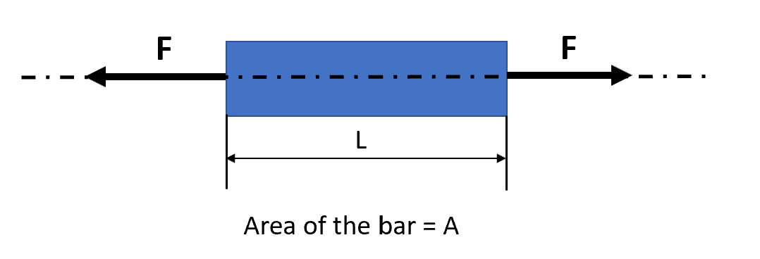
Deflection or deformation (δ) of a uniaxially loaded bar with a constant area of cross-section is given by the equation:
δ = PL/AE
where,
P = Load applied
L= Length
A = Area
E = Young’s Modulus
The typical values for Young’s Modulus are shown below:
Young’s Modules of Steel = 210GPa
Young’s Modulus of Aluminum = 70GPa
We can conclude from the above values that Steel is three times stiffer than Aluminum.
Going back to the question, for two bars with same exact dimensions as each other and with the same amount of force being applied along its axis, but different materials i.e. Steel vs Aluminum, it can be concluded that the aluminum bar will deflect 3 times more than the steel bar.
Part 2 is on the way….!