Note: The answers to these questions are based on the information I found online through various websites, YouTube videos and books. I have tried to explain the concepts in my own words.
Q6. How can a deflection of a cantilever beam be reduced?
A6. This is sort of a vague question because the interviewer has not mentioned anything about the load case on the cantilever beam such as a point load acting on the end, or in the middle of the beam etc. Also, we know nothing about the condition such as if the beam is fixed on one end, simply supported on one end etc.
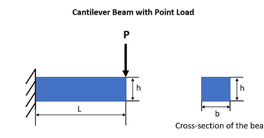
For the sake of simplicity, let us answer by assuming that the cantilever beam is fixed on one end and there is a point load acting on its other end as shown in the example below:
This is a beam with the Length L, Height h, Width b.
The load acting on the beam at the end is P.
Let us assume the beam’s Young’s Modulus is E and Area Moment of Inertia is I.
The maximum deflection of a cantilever beam is given by the equation:
δmax = (P * (L^3))/ 3 * E * I
Using the formula above, below are some ways to reduce the deflection of the beam:
Option 1. By decreasing the load (P) applied on the beam
Option 2. By decreasing the length (L) of the beam
Option 3. By increasing the stiffness of the beam i.e. Young’s Modulus (E)
Option 4. By increasing the area moment of inertia (I) of the beam given by I = bh^3/12
Q7. Does bending stress in a beam depend on Young’s Modulus?
A7. The answer is YES! Bending stress is dependent on Young’s Modulus. Since Young’s Modulus is the stiffness of a material, higher the Young’s Modulus, lower the bending (deflection) of the beam. There would be more resistance to bending which means there would be more internal forces developed (and as a resultant bending stress) to resist the bending.
Phew that was easy! 😅
No gibberish equations unlike the previous answers……. or is it?
Now shall we study in detail the concept of Bending Stress?
Bending Stress is the stress generated in a beam that is undergoing deflection.
Bending Moment is the reaction induced in the beam when an external force acts on the beam, causing it to bend as shown by the orange arrows in the image below.
It must be noted that the fibers on the upper portion of the beam tend to get shorter by undergoing Compression, whereas the fibers on the lower portion tend to get longer by undergoing Tension, as represented in the image above.
Although there are fibers along the neutral axis that passes through the centroid of the beam, that remain neutral (as in neither shorten, nor extend).
In order to quantify the Bending Stress and Bending Strain developed in this beam, let us assume this is perfect case of pure bending, which means we could create represent the geometry of bending in the form of a circle as shown in the image below.
Note: I did not do a very good job of drawing the arcs perfectly in the image, sorry about that! Please look for images online that but the idea is that the beam bends in the form of a circle (ideal case of pure bending)
Please note the following from the image above:
1. E is the center of the circle
2. R is the radius of the arc to the neutral axis
3. θ is the angle of the arc
3. A & B are two points on the neutral axis
4. C & D are two points that are away from the neutral axis by a distance y.
Note that the distance y is defined positive downwards in this case (but you can also consider y to be negative in which case the Bending Strain sign would be negative)
Let us calculate the following:
Length of the arc AB = R x θ
Length of the arc CD = (R + y) x θ
In the answer to first question, we looked at the definition of strain.
Strain is the change in length divided by the original length given by the equation below.
ε = ΔL/L
From this equation, we can form another equation to calculate the Bending Strain:
ε = ΔL/L = (CD - AB) / AB = [((R + y) x θ) - (R x θ)] / (R x θ)
Therefore, Bending Strain can be given by the equation:
ε = y/R
Next step is to calculates Bending Stress.
Let us apply Hooke’s law by assuming that the stress & strain are within the elastic limits.
By Hooke’s law, stress is proportional to strain:
σ = Eε
Therefore, Bending Stress equals:
σ = (E x y)/R
So we have successfully calculated Bending Stress and Bending Strain!
But how do we relate Bending Moment to Bending Stress? Bending Moment (M) is given by the equation :
M = (E x I) / R,
where I is the Area Moment Of Inertia
This equation come from integration and unfortunately, I am not very good with integrals, so I am unable to explain the integration concept as to how we end up with the equation above for Bending Moment. Your best bet is to google it!😅
Therefore, from all the above equations, we can define a relationship between Bending, Stress & Bending Moment as follows:
σ = (M x y) / I
We now obtain what is called a Flexural Formula as shown below:
σ / y = M / I = E / R
Q8. Compare the stress-strain diagrams of Aluminum vs Steel
A8.
Q9. Explain the phenomenon of Strain Hardening and Necking
A9. Let’s look at the stress-strain curve for a material, say Steel to explain what Strain Hardening and Necking mean.
From the curve below we can say that the Plastic region of the stress strain curve can be categorized into two regions: Strain Hardening & Necking.
Strain Hardening is when the material is strained beyond its yield point or yield strength. The material tends to harden (permanently deform) to resist any further deformation. As you can see from the curve, the strain of the metal increases after crossing the yield point, up until the ultimate tensile strength of the material.
Necking can be described pretty much as the narrowing of the material as you keep pulling it (applying load F in both directions as shown below) to a point where it fractures.
Q10. Concepts of Brittle vs Ductile materials; Ductility, Toughness and Resilience of materials.
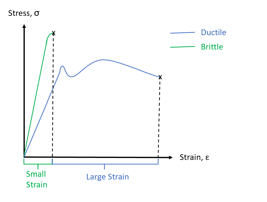
A10. Ductility is the ability of a material to deform plastically before it fractures. Ductile materials undergo large amounts of plastic deformation before they fracture, whereas Brittle materials undergo very small amounts of plastic deformation (strain is less than 5%)
Gold is an example of a very ductile material as it fractures at large amounts of strain, whereas Glass is an example of a very brittle material that fractures at low amount of strain with little to no plastic deformation.
Toughness is the ability of a material to absorb energy up to fracture, while Resilience of a material is its ability to absorb energy during elastic deformation. These two properties of a material can be represented by the area under the stress- strain curve.
Ductile materials have high toughness when compared to Brittle materials. Low strength materials and brittle materials have low toughness.
Part 3 is on the way…!


